20+ Ice Maker Wiring Schematic
Refrigerator Bucket and Auger Assembly. Web Download owner manual for Norcold 120X-IMXX 1200XX.
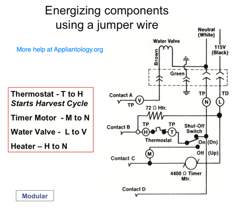
Appliantology
Web 2 Remove the Ice Bucket.
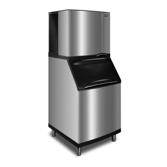
. Web The Service Manual contains product overview information troubleshooting and diagnosis help wiring diagram details major component breakdown and parts. Learn more about Replacement Parts Wiring Diagram and Pictorial Ice Maker Wiring Pictorial and Diagram Optional. Web 14020 120 20 160 20 220 20-6 to 3-4 to 3.
Web View and Download Frigidaire FFHS2313LP wiring diagram online. Shop Our Huge SelectionFast ShippingDeals of the DayRead Ratings Reviews. Web The Frigidaire ice maker wiring diagram is designed to provide you with all the information you need to properly install your Frigidaire ice maker.
355 Diagram Number. 4 Remove Fill Cup and Icemaker Insert. 60 psi 41 bar.
Switch connector orientation does. 20 psi 14 bar Maximum incoming water pressure. FFHS2313LP refrigerator pdf manual.
7 Adjusting the Ice Cubes Level. 3 Remove the Existing Icemaker. Service and Wiring Sheet - W10641015pdf Author.
The left side of the condenser rolled into an end tube. Web Page 1 SERVICE AND INSTALLATION MANUAL THE ICE SERIES CUBERS ICE0250 through ICE2100 SERIES Includes Undercounter and 22 Inch Series ICE-O-Matic. The most common location is listed below.
Web The wiring diagram mini-manualschematic is packaged with each model. Of 14 635 mm OD soft. 354 Diagram Number.
Web ice maker wire harness to the switch in new module cover. Your wiring diagram should be behind the lower kick plate or taped to the bottom of the machine in a. Web The schematic will show the exact wiring for the ice maker including the main power supply the ice maker control board the water pump and the ice maker.
Web Wiring Diagrams Page G1 Cuber Performance Data Page H1 Specifications Page I1. Ice maker cycle must be initiated. Ice Water - aUtOMatic deFrOst side BY side - r134a.
5 Install Fill Cup and Icemaker Insert into New Icemaker. 5 Adjusting the Ice Cube Thickness. Ice maker and water valve not original equipment on all models.
Murray Utah 84107 United States. Connect H-Tap connector to ice maker module as shown. Web The most common type of wiring diagram is the schematic diagram which is a map of the electrical components in your ice maker and their connections.
Web 2 INSTALLATION INSTRUCTIONS Unpack the Ice Maker Removing Packaging Materials Remove tape and glue from your ice maker before using.

2

Manuals Plus
Researchgate
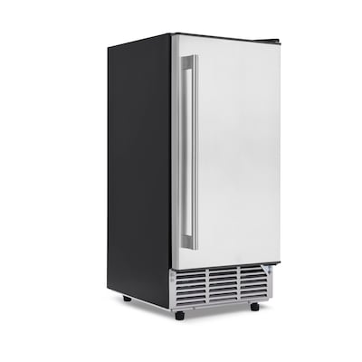
Lowe S
Visual Capitalist
Appliance Repair It Com
2

Acs Publications American Chemical Society

万博体育manbetx登陆

2

Aeropost
The Appliance Clinic

Intel Community
Appliance Repair It Com
Jspayne
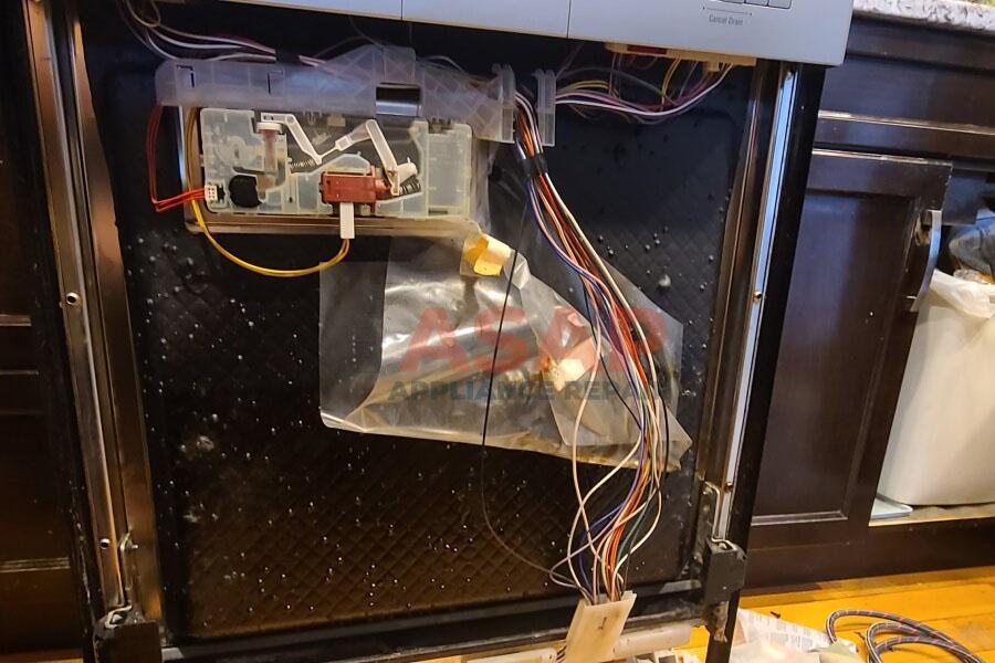
Asap Appliance Repair

Justanswer